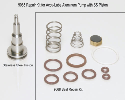
| ALUMINUM PUMP SEAL KIT Part # 9668 Seal and spring kit Part # 9065 Seal and spring kit with S.S. piston |
Instruction Sheet
|

The Kit Includes:
Part # 9668 Seal and spring kit
Part # 9065 Seal and spring kit with S.S. piston
Is Your Accu-Lube Pump Compatible?
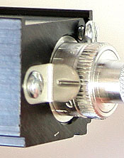 |
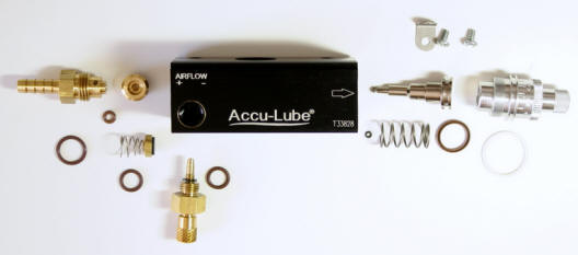
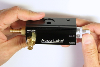
NOTE: The pump repair kit is only compatible with Accu-Lube pumps identified by a ratchet clip (#11) on the back side of the aluminum knurled oil adjustment stem. Pumps built prior to this are not serviceable. The lubricant adjustment knob (#10) is calibrated specific to the individual pump body. Ensure that the lubricant knob is assembled to the original pump body. |
Illustration
#	REQ	KIT 	DESCRIPTION
1	1	1	O RING .750 I.D. X .062, VITON
2	1	1	U-CUP 1/2 I.D. X 1/16 VITON
3	1	1	RETURN SPRING
4	2	3	O RING .301 I.D. X .070, VITON
5	1	1	O RING .065 I.D. X .035, VITON
6	1	1	EVAC VALVE
7	1	1	CONICAL EVAC SPRING
8	1	2	O RING .114 I.D. X .070, VITON
9	1	1	O RING .426 I.D. X .070, VITON
10	1	 	LIQUID ADJUSTMENT STEM
11	1	 	RATCHET CLIP
12	2	 	6/32 PAN SCREW
13	1	 	PUMP BODY
14	1	 	O RING RETAINING RING
15	1	 	1/8" PISTON
16	1	 	OIL LINE SLEEVE
17	1	 	HOSE BARB OUTLET
18	1	 	AIR ADJUSTMENT STEM
19	1	 	ADAPTOR
20	1	 	E-CLIP
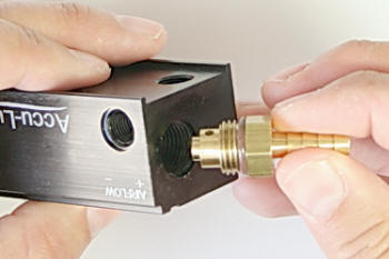
1. Remove
items 18/19 (air adjustment stem) to replace item 4 (o ring) / set aside.
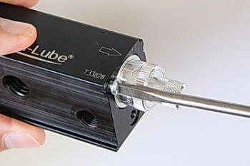
2. Remove
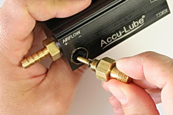
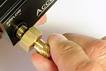
item 17 (hose barb) and replace item 4 (o ring) / set aside.
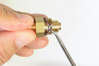
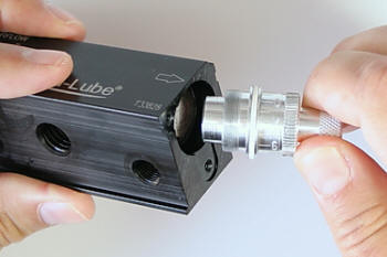
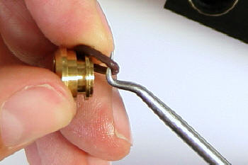
3. Remove
items 11 and 12 (ratchet clip and small screws) / set aside.
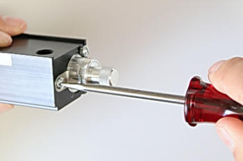
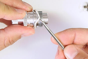
4. Unscrew
item 10 (knurled aluminum oil adjustment knob)
IMPORTANT NOTE: ITEM 10 IS
CALIBRATED TO THE SPECIFIC PUMP BODY KEEP TOGETHER WITH BODY!
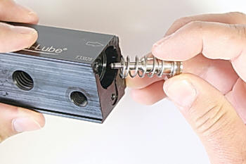
NOTE; REMOVE ITEM 10 SLOWLY
TO PREVENT ITEM 15
(PISTON) FROM BEING DAMAGED.
ITEM 3 (RETURN SPRING) WILL
EJECT ITEM 15 UPON REMOVAL OF ITEM
10.
NOTE; ITEM 15 IS A PRECISION PART HANDLE WITH CARE
5. Replace items 2 (u-cup) and 5 (O ring) on item 15 (piston) set aside
6. Replace
item 1 (large o-ring) on item 10 / set aside
6a. Replace item 4 behind item 14 "difficult"
(click to see
detail instructions).
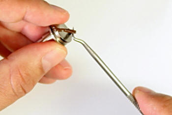
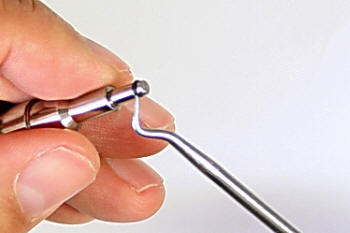
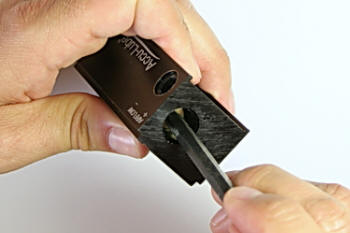
7. Using
a 3/32 O.D. stem tool, insert into large diameter hole, through piston hole,
forcing out items 6 (evac valve), 7 (evac spring), and 14 (o ring).
8. Replace
item 4 (o ring) on item 16 (oil line sleeve).
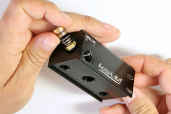
9. Re-insert
new items 6 & 7 (evac valve and spring)
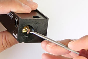
10. Insert
item 16, NOTE; press fit with a tool, until snug and stays in.
11. Insert
new item 8 (o ring) into recess of item 16 (oil line sleeve).
12. Re-install
item 17 (only until finger snug).
13. Re-install
item 18/19. Tighten with a 9/16” wrench.
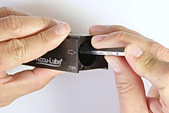
14. At
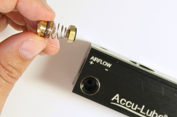
opposite end, re-install item 15 with new item 3 (return spring).
15. Re-install
item 10 (oil adjustment stem) to stop.
NOTE; DO
NOT CROSS THESE VERY FINE THREADS!
16.
Re-install items 11 (ratchet clip) and 12 (small screws).
You are
done
|
|